Welcome to my tutorial on how to make led cube 4x4x4 with Arduino Uno.
In this page I just hope to give you a little bit of clarity. Maybe some tips or tricks kind of what you need how to build this cube. Which is pretty sweet you can see.
In the description of it working so that’s going to be the final product. But in this one I’m going to show you how to make it so without further ado.
Lets’s start!
The LED cube consists of four 4×4 matrices (horizontal layers). All the LEDs on each layer are connected to one another by anodes that are wired to the А1, А2, А3, А4 pins of the Arduino NANO board.
The cathode legs of every LED are soldered together to form the vertical columns of 4 LEDs, each of which is connected to the pins L11 – L14, L21 – L24, L31 – L34, L41 – L44.
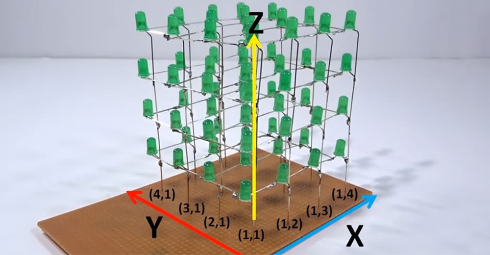
Specifics:
- The module is powered by the Arduino Nano module or an external power supply unit (5 volts) connected to the port on the control board.
- As it happens, schematics of various manufacturers of Arduino-like modules differ from the original Arduino NANO. We took this into consideration when developing the proposed extension. The original microcontroller module is installed in the left ports, while the DFRduino module, for example, is installed in the right ports. Differences between modules can be found in our circuit diagram.
- Practically any infrared remote control in your house can control your cube.
What the assembly will require
Radio assembling tools and materials: soldering iron, side cutters, tweezers, solder, soldering flux.
What you will need:
- Arduino Nano (v3.0)
- 4 x 100E 1/4 W Resistor
- 64 x 5mm Green LEDs
- Female Headers
- Vero Board
How to make led cube 4x4x4 assembly instructions: step by step
Step 1. Making the LED jig
On wood board keep 20 mm gap between two lines:
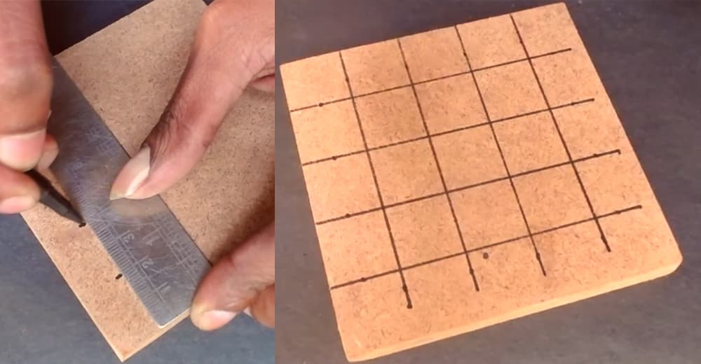
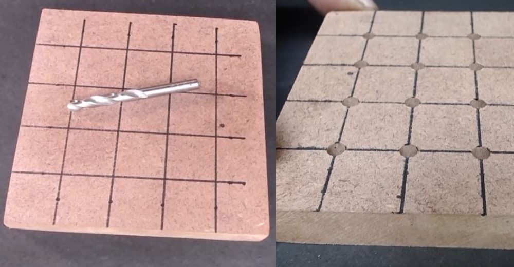
Use 5/16″ drell bit for LEDs holes:
Step 2. Making the LED cube layers
Start by preparing the leads of the LEDs.
Bending all 64 LEDs negatives (Cathodes) Lead by tweezers.
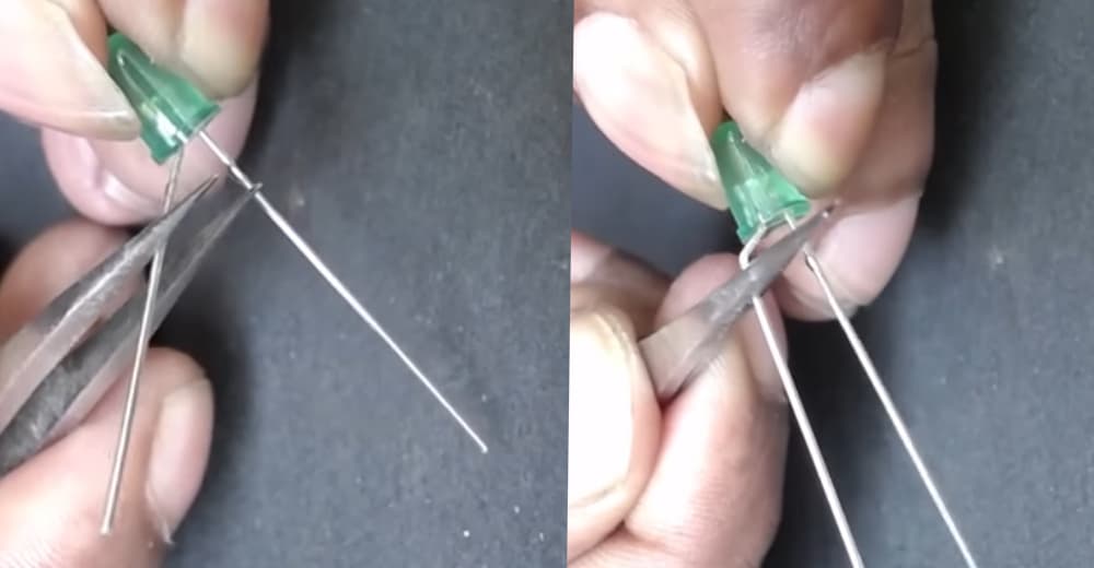
Insert 16 LEDs into the holes and bend the all positive leads:
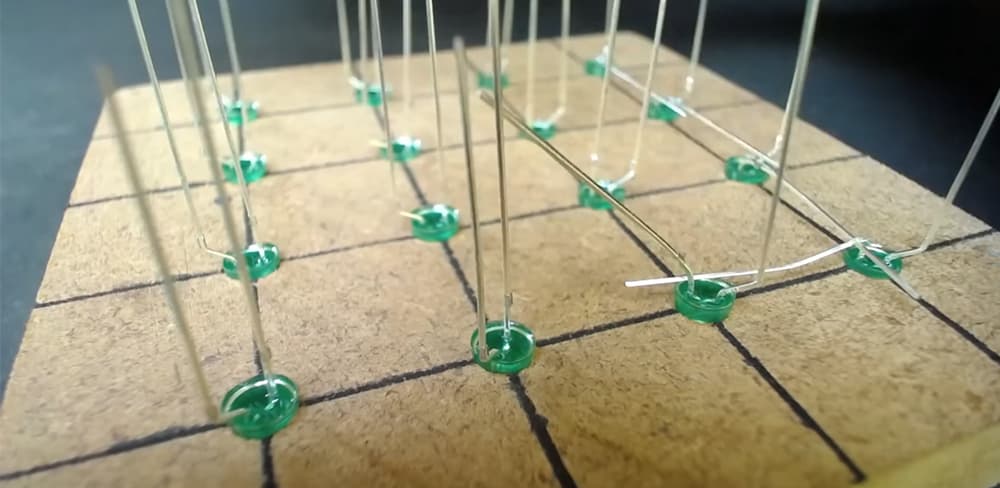
Cut the extra leads and solder all of the positive leads together
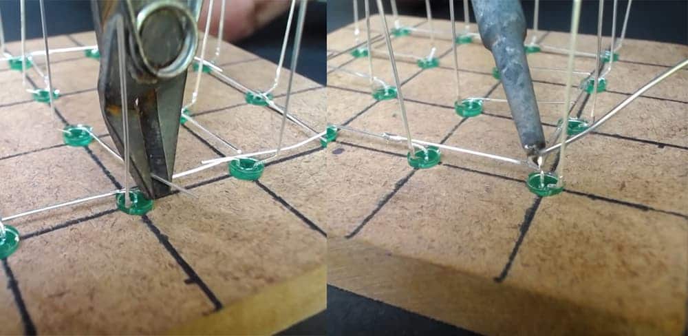
Now out first layers structure from the holes in the jig
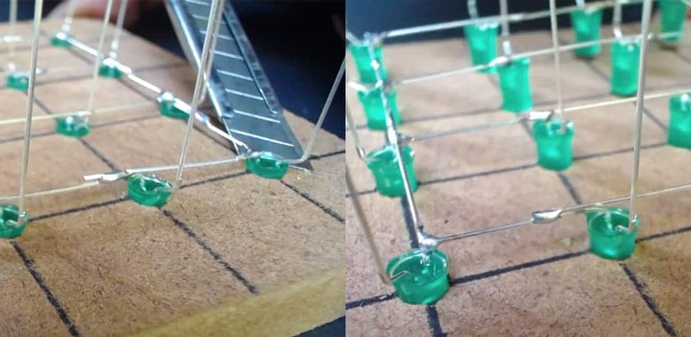
Then the second row.
Solder long leads in the second, third, and fourth row.
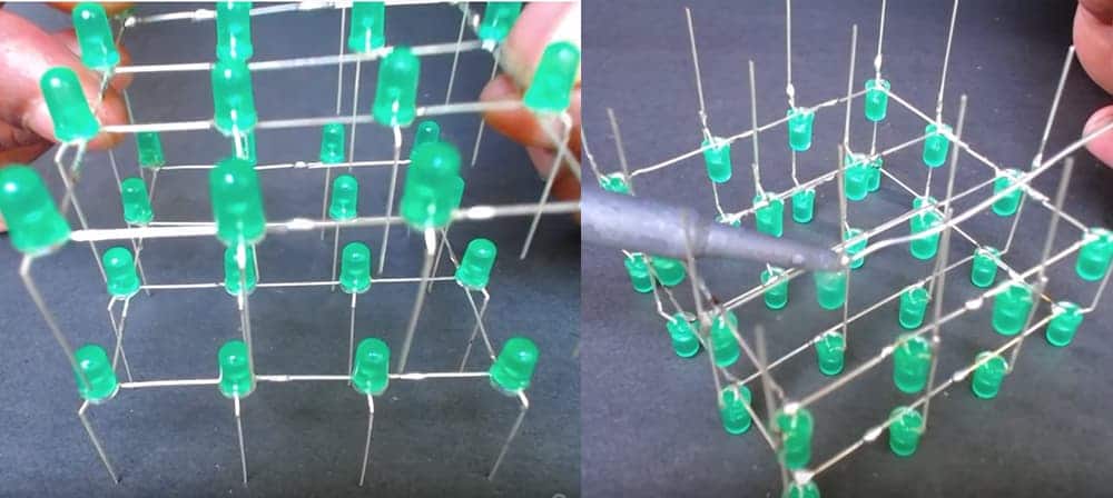
Long leads of the extreme LEDs of each row stick out beyond the edge of the board. Gently bend them along the board and connect them by soldering
Here we have one layer of 4×4 LEDs.
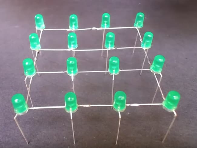
Step 3. Making the LED cube.
You can align it using additional pieces of wire.
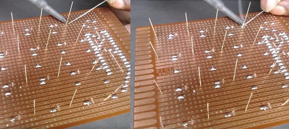
Complete four layers. Carefully install the first layer on the control board, inserting the leads of the LEDs into the holes L11-L14, L21-L24, L31-L34, L41-L44. First, solder the corner leads.
Align the layer in one plane at the corners, warming the leads up with a soldering iron and moving them up and down (if needed). Once you have made sure that the corner LEDs are in the same plane, solder the remaining leads.
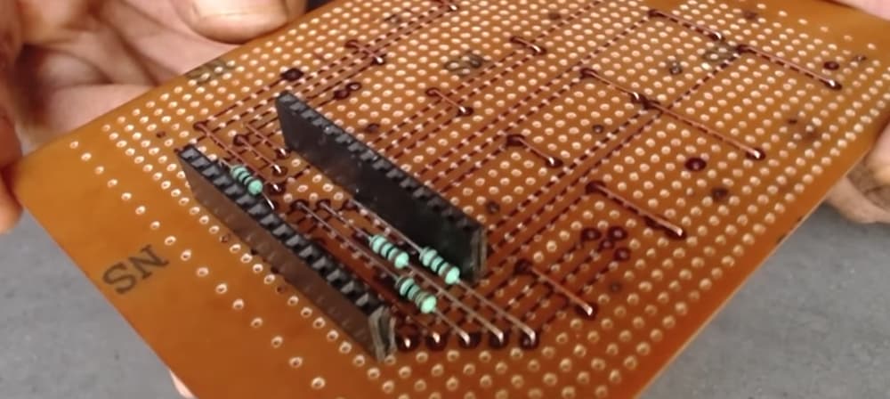
Step 4. Wiring the Circuit. After wiring:
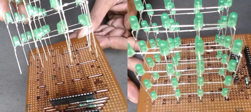
Installing the LED cube:
Step 5. Installing the Arduino / power supply
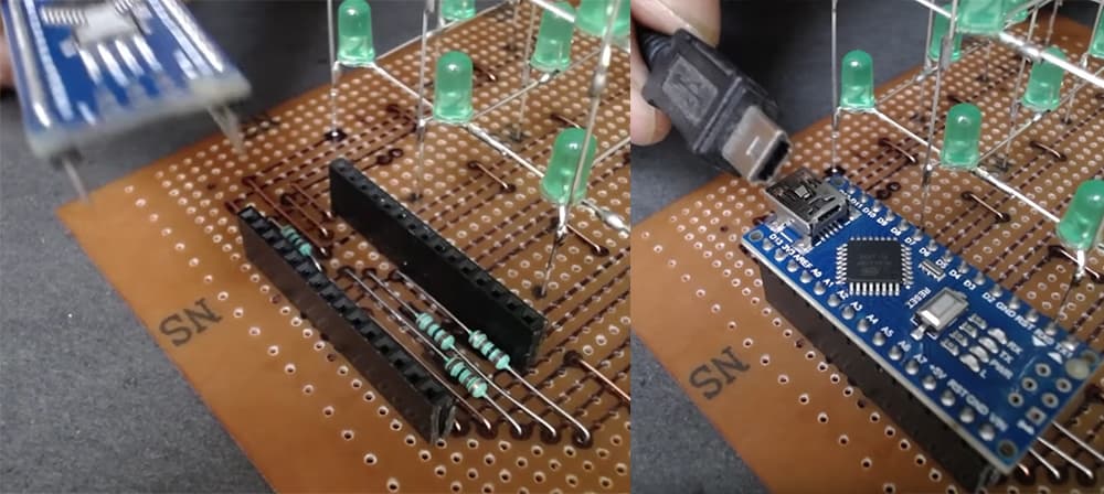
Step 6. Installing Arduino Nano Code and lets tests the Cube!
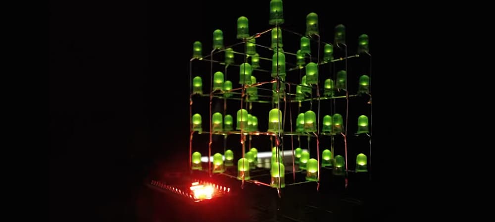
Assembly sequence
- Select the desired operating mode of the input / output channels.
- Solder the USB port if needed.
- Solder the pin headers if you need them.
- To use GPIO in INPUT mode, jumper pins 2 and 1 on connectors J1 or J2. To use GPIO in OUTPUT mode, set the jumper between pins 2 and 3.
- Resistors R6 and R8 are not installed, an external relay with a 5 Volt winding can be connected to pins 2 and 3 of pin headers J8 and J9.
- If you need to use the outputs in logical mode – install resistors R6 and R8.